Before I got back into photography with the amazingness that came with the digital camera revolution, I had always looked from afar at the older Canon L lenses and their fancy red rings. These pro lenses have always been out of reach for me financially, since it doesn’t make much sense for a hobby photographer to go and blow $1,400 on a lens.
But, I’ve finally caved in and bought one. Not a new nice lens, heck, not even gently or heavily used but working lens. I decided to get a clapped out, bottom of the Ebay barrel, broken and non functioning used lens. Hooray! This older 28-70mm came from a fellow in New York who trained parrots, so I’m not sure what it may have experienced in its life span. Its zoom function was very stiff as if it was binding on something, mostly it did not like to reach the stop at the 28mm side, also the auto focus was not working and would go “clack clack clack clack” when trying to focus jumping all around never reaching its target.
The lens in good physical condition for something that has not been made in at least 13 years (production ran from 1993 to 2002), and has no fungus or glue separation issues on the glass, just mechanical problems. So I figured, what the heck, lets try to fix it.
First thing I did was try to read up on what type of USM drives Canon used in their lenses, and also what the heck a USM drive actually is. What I found out is Ultra Sonic Motors operate on vibration, hence them being ultra sonic. This means that the focus motor runs the camera lens like one of those old vibrating football table games. From this ultra high frequency it can run the motor forward and backwards depending on what wave it generates. I’m not going to go into this to much further here, but if you interested in finding more Wikipedia has a bunch of info on it that is really interesting, or hit up my original thread over at FredMiranda.com, some users over there had some good info.
I then started trying to source some parts to fix my lens. But since the 28-70mm has not been made in so long, all the parts are out of production and Canon no longer services it. This got me thinking, since the USM focus drive motors seemed like a very expensive thing to have placed into production, it would not make since for Canon to redesign them for every lens. The research and development on that would be crazy, plus why make new focus motors for your other lenses if you have a perfectly good working one in production? From what I’ve found this is about what Canon thought too, they only have two motor sizes of USM drives they make. A 62mm and a 77mm, the 77mm motor being the one I assume is used in all larger L based lenses (don’t quote me on that, its just a guess). Also the other lenses USM drives appear to only have different shaped or length ribbon connecting to the motor.
So, I took a chance and ordered a USM drive/motor for a newer lens, the Canon EF 24-70mm F/2.8 L USM -Part# YG2-2064-000
As luck would have it, the motor and ribbon cable on the newer lens are exactly the same as its older 28-70mm brother. So, here’s how to replace it.
(NOTE, if you decided to tear your expensive lens apart and manage to mangle it somehow, its not my fault. Also replacing the USM drive will not fix all focus problems, lenses are complicated, lots of things can break).
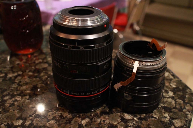
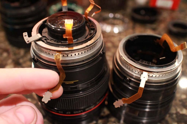
1. Here is the 28-70mm next to the 24-70mm’s focus motor assembly. Gives you a rough idea how the part fits within the lens.
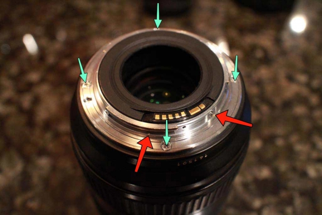
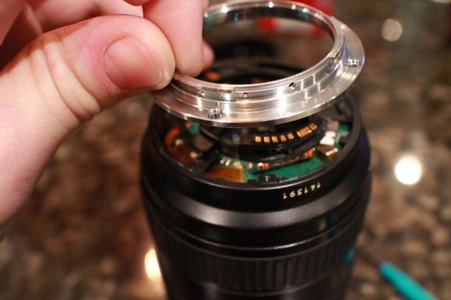
2. Time to tear into it. Using a set of JIS micro screwdrivers (don’t use standard phillips screw drivers, they will just strip the heads), take out all arrowed screws.
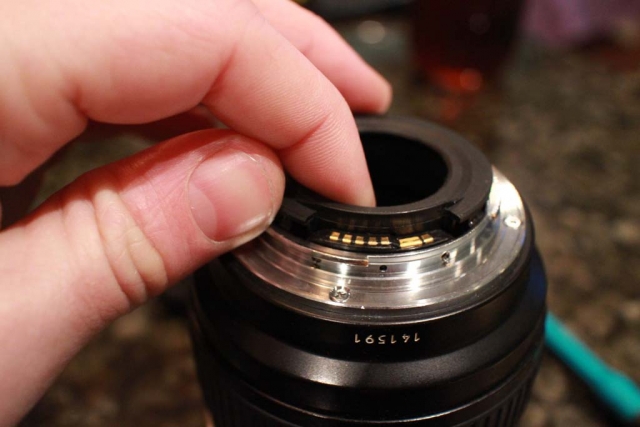
3. Pop the center ring out by pulling straight up on it, make sure to keep some pressure down on the lenses rear mount flange so you don’t damage lenses contact connector.
4. Lifting the rear mount off.
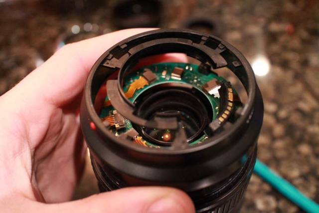
5. Next section comes straight off now exposing the lenses PCB.
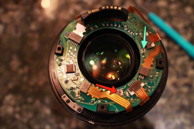
6. The lenses PCB. Red arrow is the USM motors pulse setting screw. The USM stator is divided in two halfs, and ran by pulses, which are supposed to be sent in equal spacing, such as:  –  –  –  –  –  –  -. If the pulse are out of adjustment it may appear staggered or off balance such as: —– — —– — —– — —–  This is bad, Turning this screw will change the pulse spacing, but without an oscilloscope this is just kind of trial and error. Its supposed to be adjusted after changing out the focus motor or PCB, but on my lens at least it seemed to be about right even after the motor change. The blue arrow is the frequency adjustment screw which you can use to change the frequency the motor runs at. I don’t have the service manual in front of me at the moment for its intended value, but its best not to mess with this one, or if you do mark where it was set at (actually do that on both if your playing with them).
Back to tearing things apart. Lightly tug on most of the ribbons to unplug them. Release the locks on the two ribbons that use them, then just pull the PCB up and out once all is disconnected.
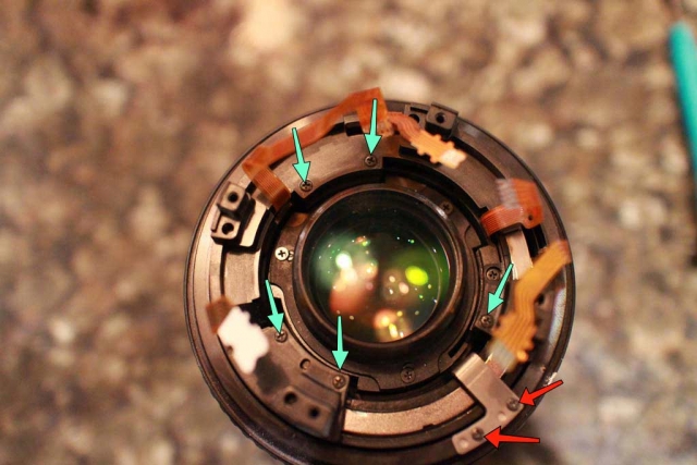
7. Remove the marked screws.
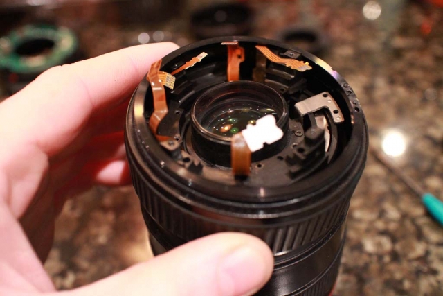
8. After removing the screws, just pull up on the barrel section feeding the ribbons through it as you go, make sure to fish it around the metal zoom stop, it will fight you a bit. Pull up the zoom ring next and slide it off in the same manner.
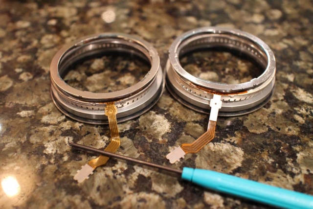
9. And here is the USM motor. Notice that the motors on the both are exactly the same, same ribbon shapes even. The top ring of the motor is glued on, so just spin it until it twists over to the release points. (I did not use glue on re-assembly, it seemed to act fine).
On my lens I ended up having to use the old rotor (bottom thick ring), new stator (notched teethy ring), new felt washer, and old spring/lock. The rotor may have been slightly taller on the newer 24-70mm motor, but I’m not sure. I will say I had to put the lens back together and tear it down around 4 times before it was happy with the combination new/old USM motor parts I picked and was working correctly. I would have to guess that USM drives are not meant to be replaced in this manner, but rather as whole assemblies which are pre adjusted and working from the factory.
Old USM motor from the 28-70mm on the left, newer 24-70mm Mark 1 motor on the right. Pretty much identical.
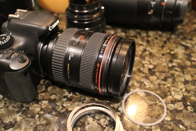
28-70mm all together on my T2i working like a champ.
So now that its back together, what do the pictures look like? Well…. odd. The lens seems to be out of collimation, especially when used at 70mm. So I took a few shots on the wide end of 28mm and they turned out okay-ish:
So the 70mm end is out of wack, its not the end of the world. Heck this way it turns things into a blurry mess that sort of look like an impressionist painting. Its not broken, its a specialty lens!
Sometime soon I’ll send it off to a repair shop for a cleaning and lens calibration, but for now its on abstract duty.

